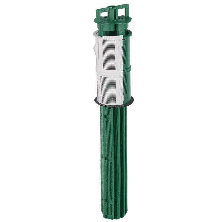
Check out the Zoeller YouTube Channel for Webinars, Tips, Trainings, and Product Videos!

X
MENU CLOSE

Spider Valve®


Spider Valve®

Drain Fields

Split flows evenly or custom drill the orifices for unequal lateral lines

  • Features and Benefits

    Zoeller Pump’s Spider Valve® assembly is the answer to appropriate distribution of effluent when regulations require pressure splitting or when small lots require lateral lines of unequal length. When combined with a pump, customizable orifices within the manifold ensure that no lateral receives more than its share of the total flow. A convenient sizing program is available online to allow for customization to any project. The Spider Valve is available in models that serve up to ten laterals. Each Spider Valve assembly includes 5/32” predrilled washers and a union for each washer. Unions allow washers to be removed for cleaning and maintenance.

    • Mounts in a 24” diameter access riser
    • 3 feet of 1/2” diameter PVC flexible pipe on each discharge for ease of assembly
    • 2” diameter SCH 80 PVC manifold with cleanout for equal pressurization and easy maintenance
    • Pressurized splitting to a gravity disposal field
    • Configurable manifold

    Notes

    For sizing assistance, please consult Technical Service at 1-877-244-9340 or download the Spider Valve® Orifice Sizing Tool to help design your onsite system.

    All Zoeller Pump products must be installed and maintained in accordance with all applicable codes.

  • Product Specifications

    1.65 GPM per outlet at 5′ distal pressure


    Discharge Size 1-1/4″
  • Literature

    Installation Steps:

    1. Spider Valve® assembly must be installed at the high point of the system such that the effluent will gravity drain from the valve to the disposal trenches. Consult site plan and Figure 1.
    2. At least 3′ of distal pressure should be maintained on the manifold to ensure equal effluent splitting.
    3. For distribution systems with unequal length disposal trench lines order the Spider Valve® with blank flow control washers. Use the following chart to determine the correct flow rate for the diameter hole that must be field drilled in the flow control washer. Glue washers into manifold connections as shown.
    4. For distribution systems with equal length disposal trenches then drill ¼” diameter holes in all washers or order the unit with pre-drilled and assembled ¼” washers.
    5. The manifold should be installed in a Zoeller Pump 24″ diameter access riser and lid (See FM1572).
    6. Bed manifold area with 2″ of pea gravel. Manifold should be installed level.
    7. The incoming line should be pressurized with at least 3′ of distal pressure. The manifold must be connected to the pump line with a 2″ female PVC pipe connection.
    8. Outlet pipes contain 3′ of flexible PVC pipe with a 1¼” diameter connection. Run 1¼” or larger pipe away and downgrade from manifold to individual trenches (check local codes).
    9. Check that all connections are glued appropriately and watertight. Backfill around manifold with pea gravel until 2″ pipe is almost buried. This will ensure the manifold does not move and stays close to level.
    10. Place access riser and lid around manifold and finish backfilling. Landscape as desired.
    Dimensional Drawing, Spider Valve_SK2322

    Dimensional Drawing, Spider Valve_SK2322


    Dimensional Drawing, Spider Valve_SK2323

    Dimensional Drawing, Spider Valve_SK2323

    Dimensional Drawing, Spider Valve_SK2323


Zoeller Pump’s Spider Valve® assembly is the answer to appropriate distribution of effluent when regulations require pressure splitting or when small lots require lateral lines of unequal length. When combined with a pump, customizable orifices within the manifold ensure that no lateral receives more than its share of the total flow. A convenient sizing program is available online to allow for customization to any project. The Spider Valve is available in models that serve up to ten laterals. Each Spider Valve assembly includes 5/32” predrilled washers and a union for each washer. Unions allow washers to be removed for cleaning and maintenance.

  • Mounts in a 24” diameter access riser
  • 3 feet of 1/2” diameter PVC flexible pipe on each discharge for ease of assembly
  • 2” diameter SCH 80 PVC manifold with cleanout for equal pressurization and easy maintenance
  • Pressurized splitting to a gravity disposal field
  • Configurable manifold

Notes

For sizing assistance, please consult Technical Service at 1-877-244-9340 or download the Spider Valve® Orifice Sizing Tool to help design your onsite system.

All Zoeller Pump products must be installed and maintained in accordance with all applicable codes.

1.65 GPM per outlet at 5′ distal pressure


Discharge Size 1-1/4″

Installation Steps:

  1. Spider Valve® assembly must be installed at the high point of the system such that the effluent will gravity drain from the valve to the disposal trenches. Consult site plan and Figure 1.
  2. At least 3′ of distal pressure should be maintained on the manifold to ensure equal effluent splitting.
  3. For distribution systems with unequal length disposal trench lines order the Spider Valve® with blank flow control washers. Use the following chart to determine the correct flow rate for the diameter hole that must be field drilled in the flow control washer. Glue washers into manifold connections as shown.
  4. For distribution systems with equal length disposal trenches then drill ¼” diameter holes in all washers or order the unit with pre-drilled and assembled ¼” washers.
  5. The manifold should be installed in a Zoeller Pump 24″ diameter access riser and lid (See FM1572).
  6. Bed manifold area with 2″ of pea gravel. Manifold should be installed level.
  7. The incoming line should be pressurized with at least 3′ of distal pressure. The manifold must be connected to the pump line with a 2″ female PVC pipe connection.
  8. Outlet pipes contain 3′ of flexible PVC pipe with a 1¼” diameter connection. Run 1¼” or larger pipe away and downgrade from manifold to individual trenches (check local codes).
  9. Check that all connections are glued appropriately and watertight. Backfill around manifold with pea gravel until 2″ pipe is almost buried. This will ensure the manifold does not move and stays close to level.
  10. Place access riser and lid around manifold and finish backfilling. Landscape as desired.
Dimensional Drawing, Spider Valve_SK2322

Dimensional Drawing, Spider Valve_SK2322


Dimensional Drawing, Spider Valve_SK2323

Dimensional Drawing, Spider Valve_SK2323

Dimensional Drawing, Spider Valve_SK2323