Popular Applications
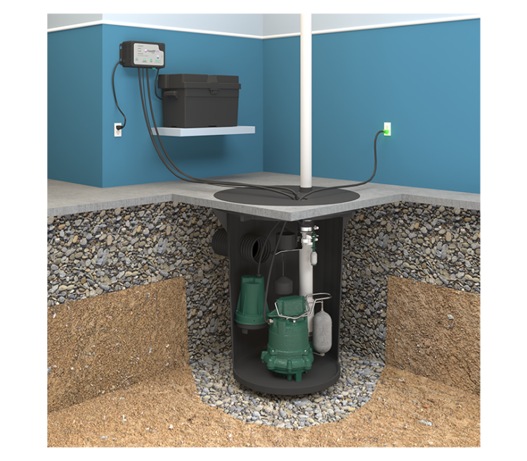
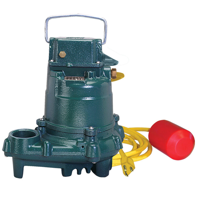
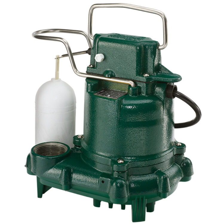
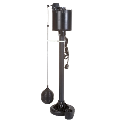
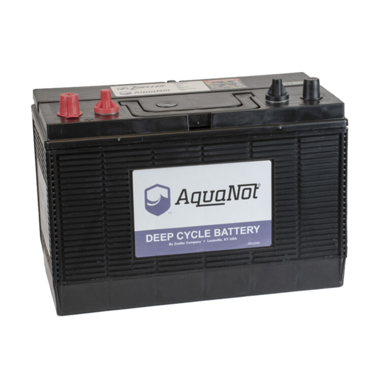
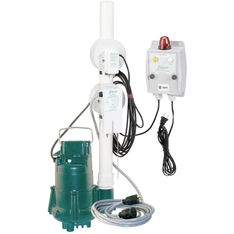
Our high-quality sump pumps and backup systems can dependably protect your home and keep you and your family safe and dry.
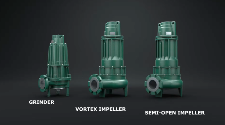
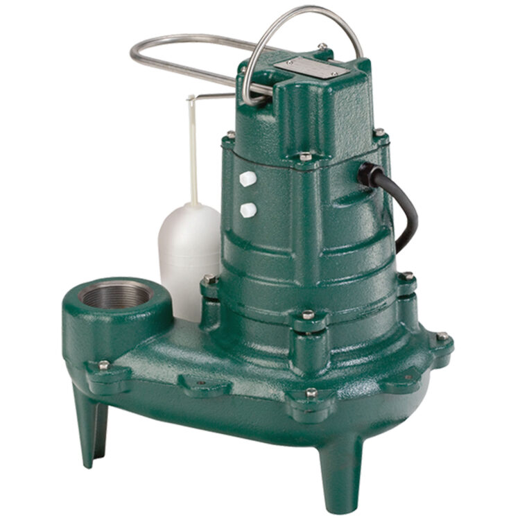
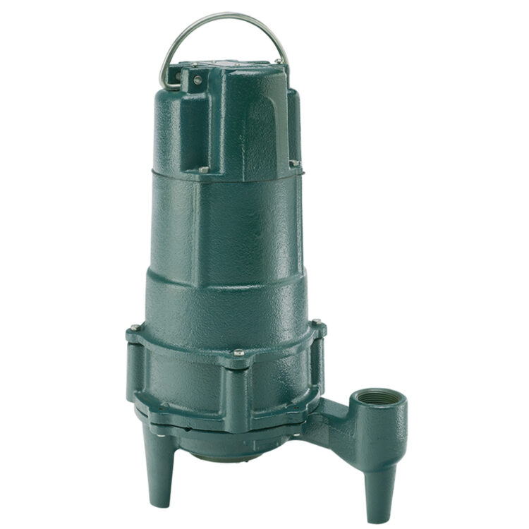
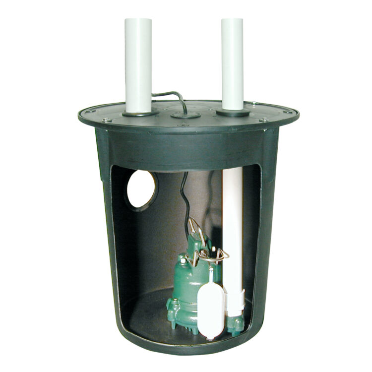
Learn MoreSewage or grinder pumps move raw sewage and unwanted water away from the home. Our pre-plumbed packages make selecting and installing the right equipment easy.
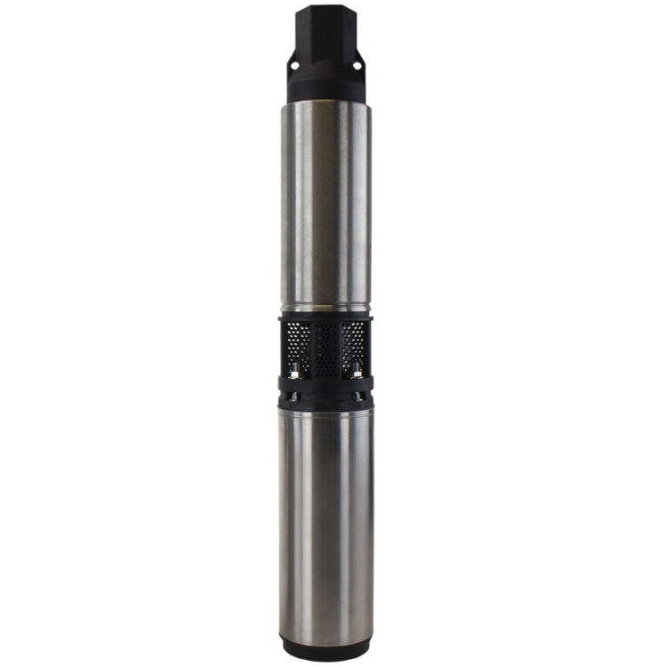
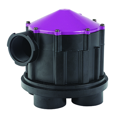
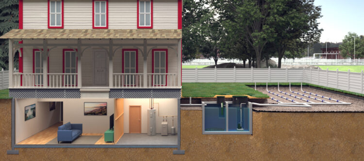
Learn MoreWhen sanitary sewers are not available, septic systems are used to treat wastewater before disposal.
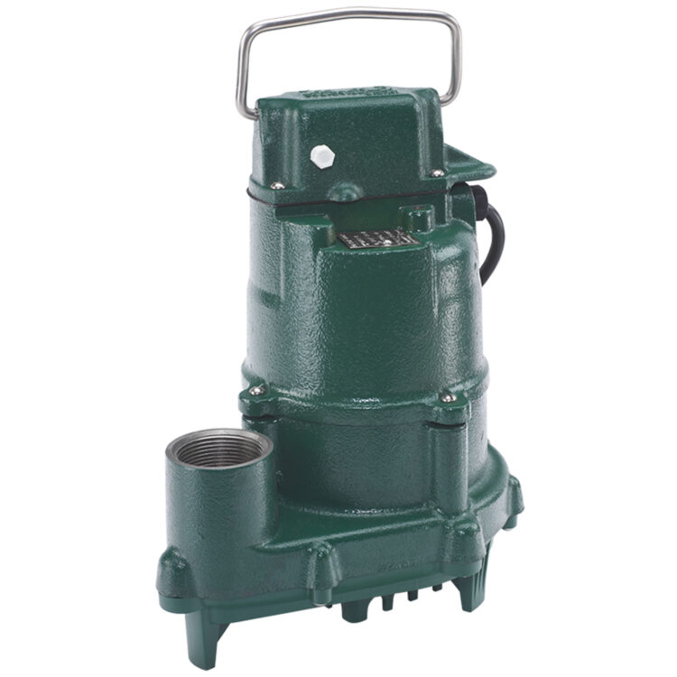
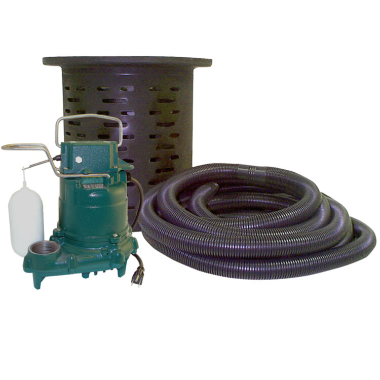
Learn MoreCrawl spaces get damp, leading to mold and structural damage. Our sumps manage moisture, preventing these issues.
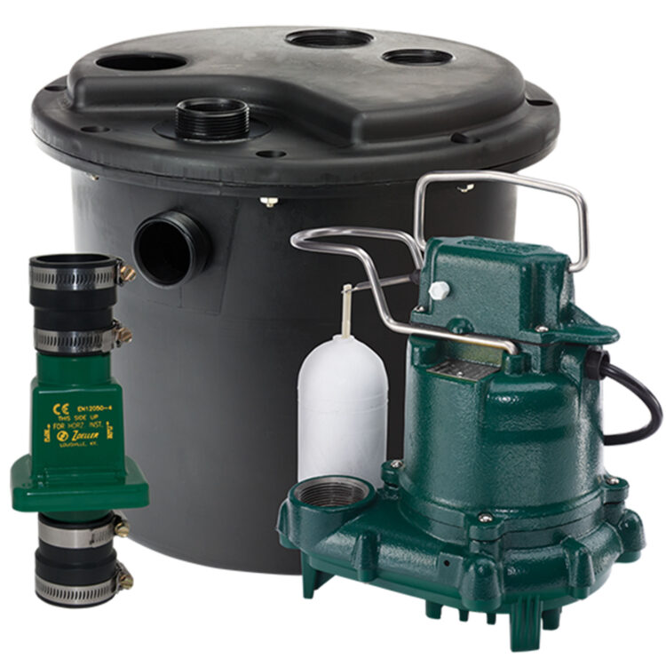
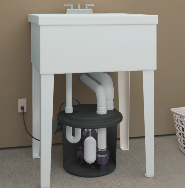
Learn MoreInstall a sink drain anywhere without breaking concrete. Use our drain pumps for easy installation in areas without gravity drainage.
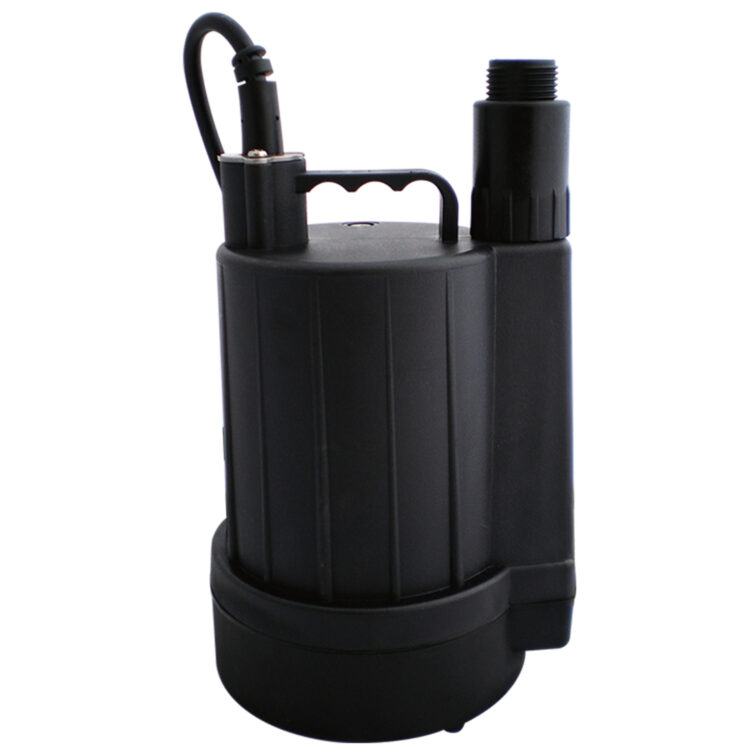
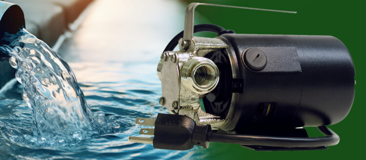
Learn MoreIdeal for draining swimming pools, hot tubs, basements, and other areas, our portable dewatering pumps are affordable and easy to transport or store.
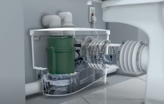
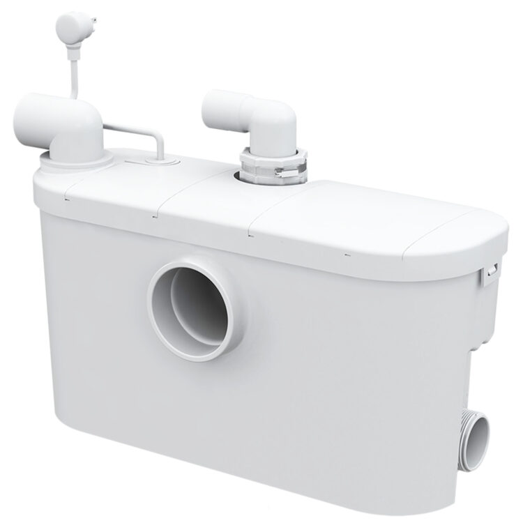
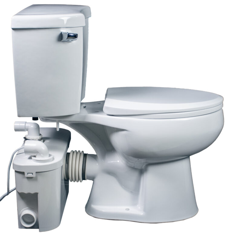
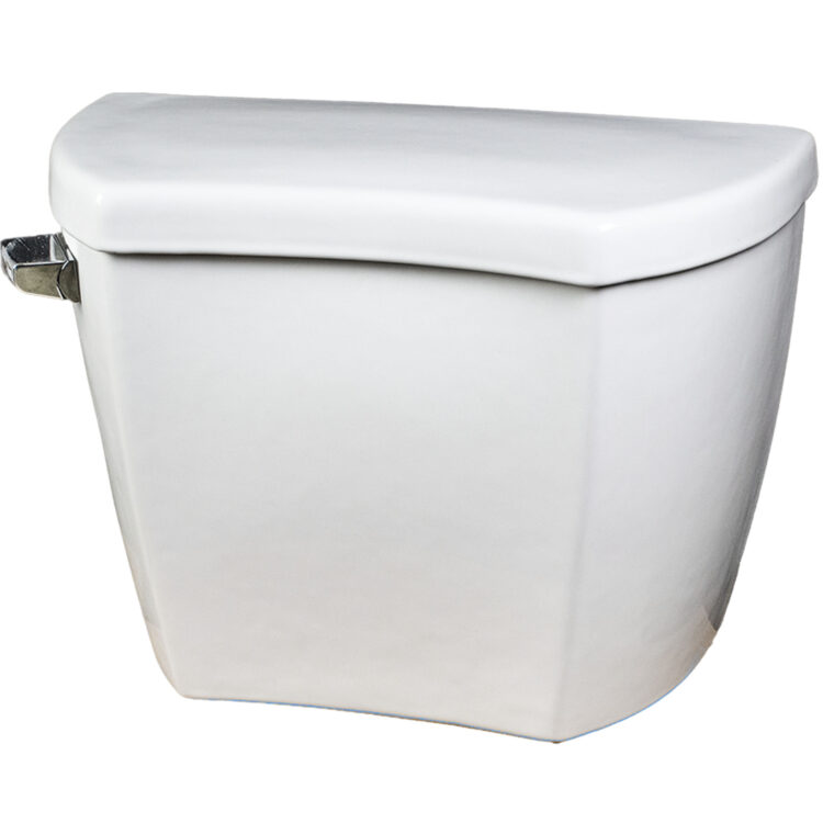
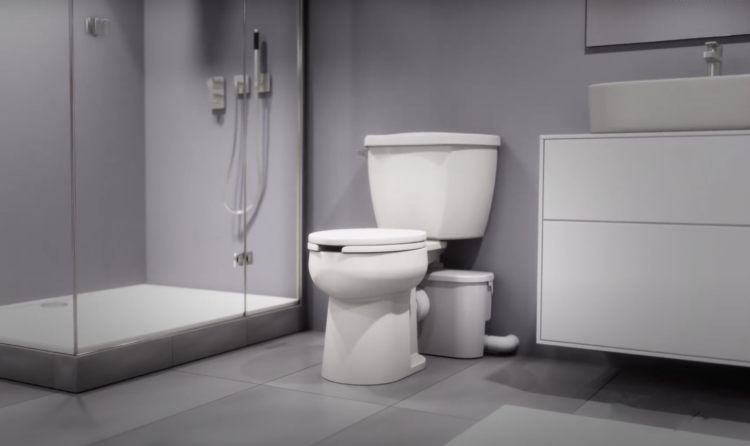
Learn MoreAdd a full or half bathroom to an area without gravity drainage by using our upflush toilet systems to avoid breaking concrete.
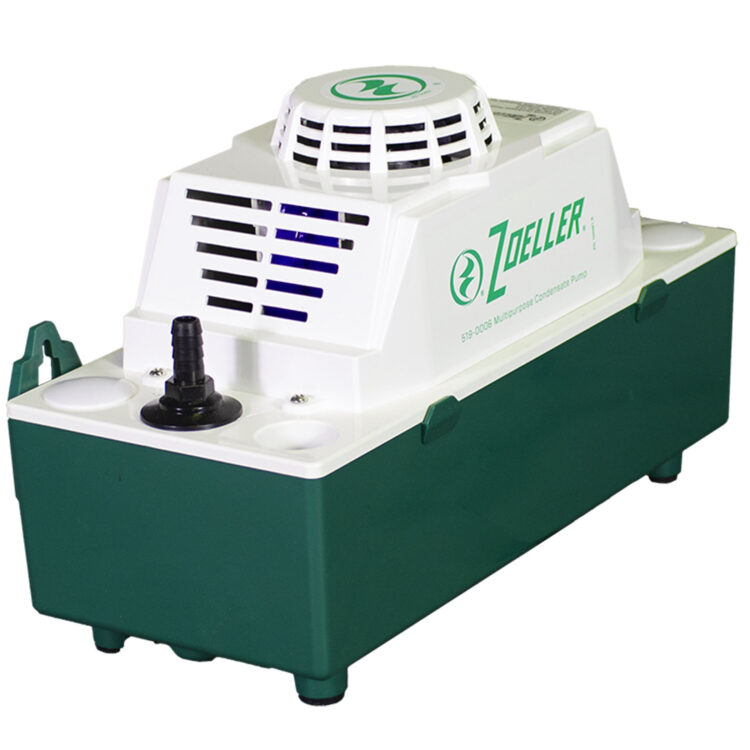
Learn MoreRemove condensation from air conditioning equipment, condensing furnaces, dehumidifiers, ice makers, water coolers, and refrigeration systems when gravity flow is not an option.
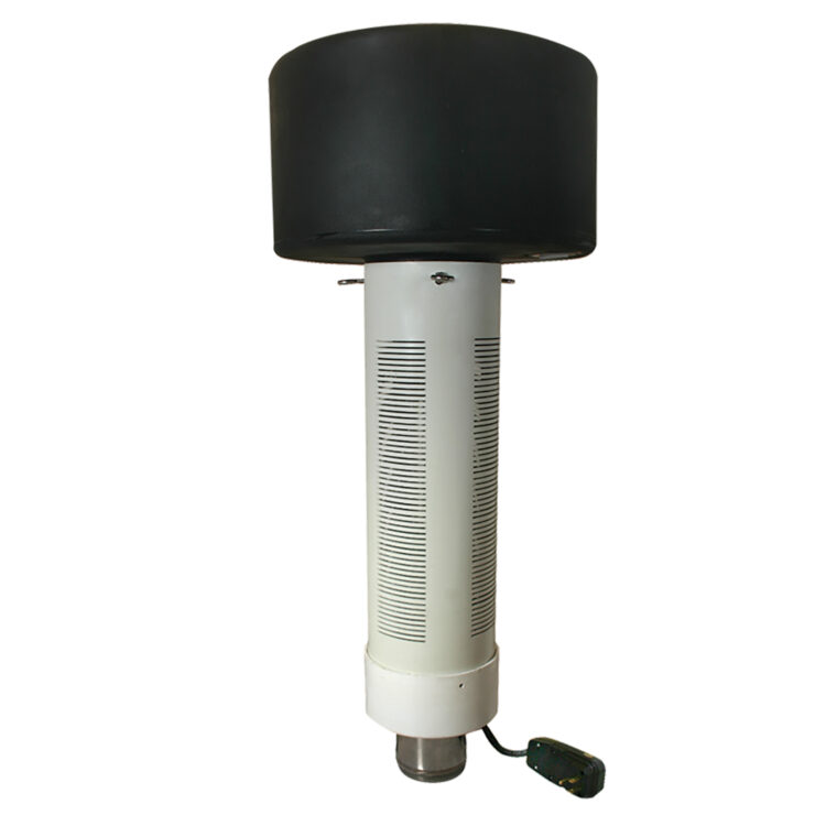
Learn MoreFountain pumps add a unique focal point and value to your property. The environmentally friendly, water-cooled motor eliminates pollution risk and pond contamination.
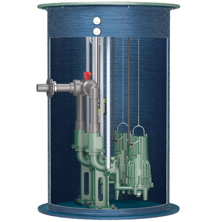
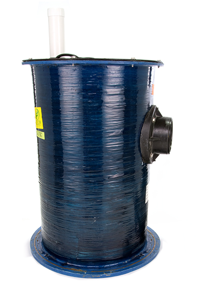
Learn MoreUnwanted water and raw sewage are pumped to an outside basin. Sewage lift station pumps take this wastewater up and away.
Learn MoreEffluent lift stations collect and pump the grey water or effluent from commercial facilities or wastewater treatment systems.
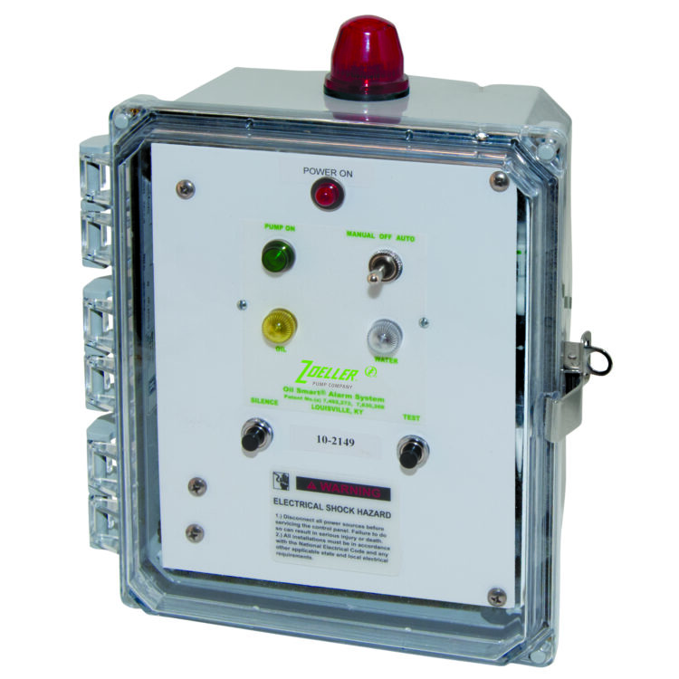
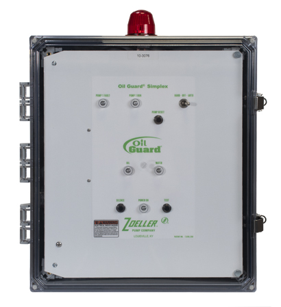
Learn MoreElevator sump pumps prevent environmental contamination before it starts by stopping the pump at the appropriate time with our oil smart system.
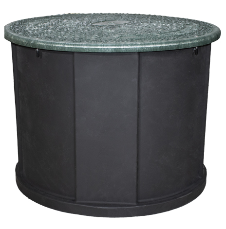
Learn MoreDuring storms, excess water can lead to flooding, pollution, and damage. We offer a range of pumps, containers, and controls to manage your stormwater effectively.
Learn MoreHome » Products
Color 1
Color 2
Color 3
Color 4
Color 5